Integrated solution · RISCO + Siemens KNX
15 m Beam Detector with Siemens KNX: PBI & Scene Control
Crossing a beam in a garden or passage triggers a defined smart-home action: path lighting, an indication or a sequence of commands. A wired integration of a transmitter/receiver pair, a dry-contact interface and a scene/event controller.
The key advantage: two beams for focused, stable detection
RISCO Beam 7115 uses a powered transmitter and receiver to establish a dedicated detection line. Requiring both infrared beams to be interrupted together is intended to reduce false alarms from birds and falling leaves, rather than reacting to a brief interruption of a single beam.
- Adjustable to the passage: An outdoor range of up to 15 m, optical adjustment of ±90° horizontally and ±5° vertically, and a 50–500 ms interruption setting allow the detection to be aligned and adjusted for the route and crossing speed.
- Clear power planning for both units: The manual lists 6 mA for TX and 16 mA for RX. Both require continuous 10–28 V DC and may be powered in parallel from one suitable supply. Each side needs a power feed, not necessarily a separate power supply.
- Targeted smart-home actions: The alarm contact reaches the PBI and event controller, enabling lighting or indication actions in response to a crossing. Commission and test the behavior under the actual installation conditions.
These advantages concern the documented detection method and adjustment. The catalogue assigns four selectable beam frequencies to Beam 72 only, not to Beam 7115. The reviewed specifications do not establish superior harsh-weather performance compared with reflector-type detectors. RISCO catalogue — detection method and series features ↗
01 / POWER
The detector needs continuous power — the PBI does not power it
Both the transmitter TX and receiver RX require a continuous DC supply. The documented Beam 7115 input range is 10–28 V DC. This reference design uses a separate regulated 12 V DC supply feeding both units in parallel. Only the receiver’s voltage-free alarm contact connects to the PBI input.
Can the Siemens 640 mA KNX supply also power the detector?
For N 125/22, order number 5WG1125-1AB22, Siemens specifies 29 V DC and an additional unchoked output. 29 V exceeds the reference detector’s 28 V maximum: do not connect it directly to either output. The 640 mA rating describes current capacity, not voltage compatibility.
An engineering option to assess is a suitable 12 V DC/DC converter fed from the unchoked auxiliary output. This page does not approve that alternative: select a converter and verify its full input range, SELV separation, protections and the supply’s shared current budget. Do not feed a converter from the KNX bus conductors or assume that the auxiliary output provides another 640 mA.
Siemens N 125/22 — 640 mA ↗02 / COMPONENTS
The three components
RISCO Beam 7115
Transmitter and receiver — beam crossing
A photoelectric pair using two infrared beams; detection requires both to be interrupted together. The 15 m outdoor rating is the optical TX-to-RX distance, not the contact cable length to the PBI.
- Outdoor / indoor range
- 15 / 30 m
- Continuous supply
- 10–28 V DC; 12 V DC in this design
- Documented consumption
- RX 16 mA; TX 6 mA; manual states ±3 mA tolerance
- Alarm output
- NC: closed at rest, open on alarm; rated up to 30 V DC / 0.5 A
- Interruption response
- Adjustable, 50–500 ms
- Environment
- IP44; operating temperature −20 to +55°C
Reference model from historical RISCO documents. Confirm availability and supplied revision before ordering; reassess power and contacts before substituting a different detector.
Siemens UP 220/21
PBI — contact state to KNX
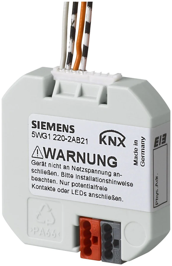
Order number 5WG1220-2AB21. Two configurable channels. In this design channel A reads the alarm contact; channel B may monitor the receiver cover tamper after its output is verified.
- Input type
- Potential-free contact; no external input voltage
- Power
- KNX bus-powered; no separate PBI supply
- Minimum input duration
- 50 ms
- Input cable length
- Maximum 10 m per channel; twisted, unshielded pair
- Location
- IP20; dry indoor installation
- Dimensions
- 42 × 42 × 8.5 mm; 11 mm at bus terminal
Install in a suitable indoor box. Do not share the box with 230 V devices or cables. Detector supply voltage must not be connected to PBI inputs.
Siemens N 305
Scene and event controller
Order number 5WG1305-1AB01. This is the controller selected for the reference design. It receives KNX telegrams and sends commands to actuators; it is not a lighting power output.
- Scene mode
- Up to 8 scenes, up to 8 groups per scene
- Event mode
- Up to 8 programs, up to 10 tasks per program
- Delays
- Scenes: 0–30 min; events: 0–120 min per task
- Mode selection
- Scene control or event programs, configured in ETS
- Supply / consumption
- KNX 21–30 V DC; 6 mA
- Installation
- DIN rail; 1 module, 18 mm wide; IP20
Select the operating mode and matching application in ETS. The event controller and the load actuator perform different functions; both are needed to operate a load.
03 / CONNECTIONS
Wiring diagrams — power, dry contact and KNX
Connections are identified by terminal function. A1/A2 and B1/B2 are drawing aliases for channel wire pairs, not printed pin numbers or wire colours. Match them to the supplied interface harness diagram. Line colours are a functional legend only.
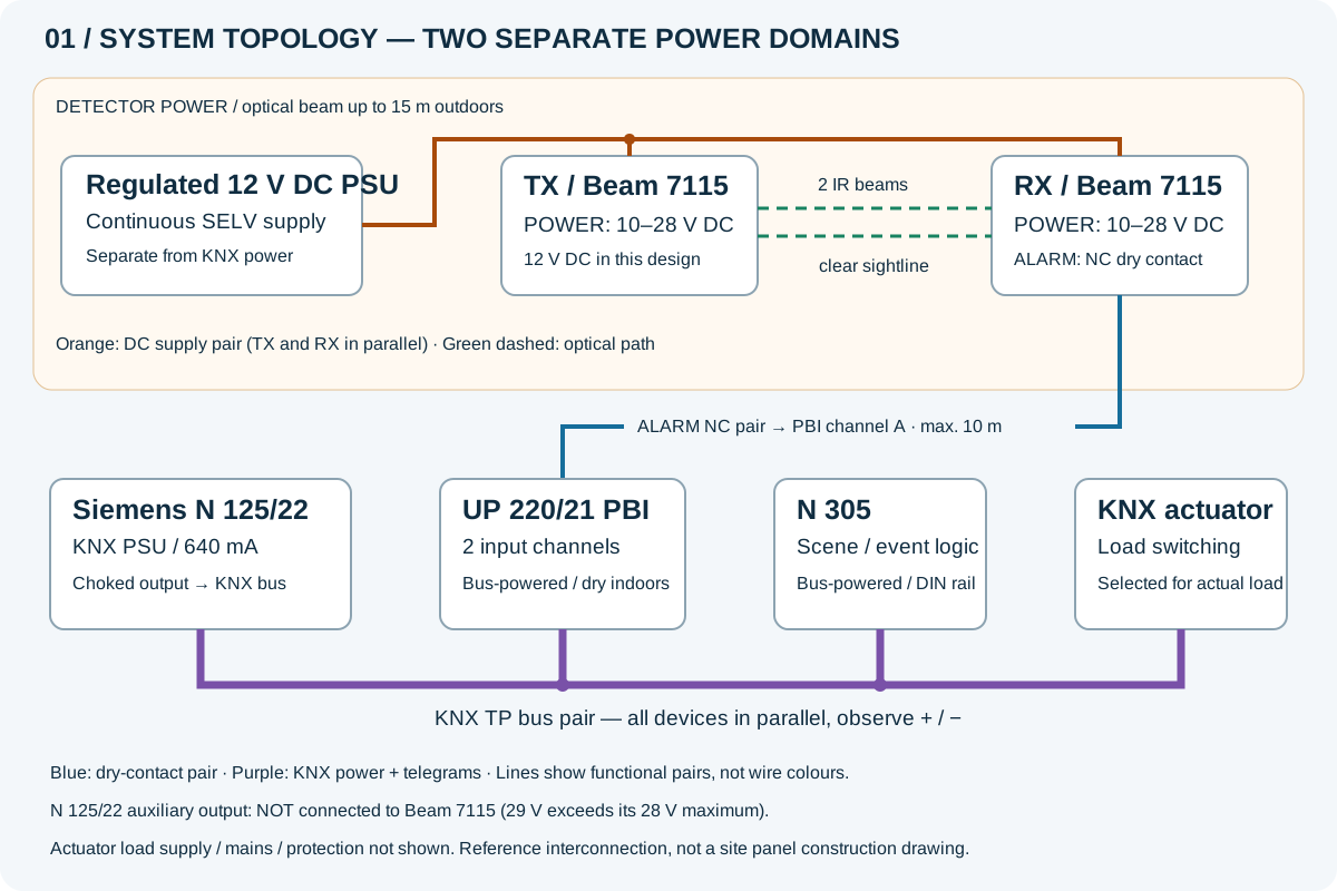
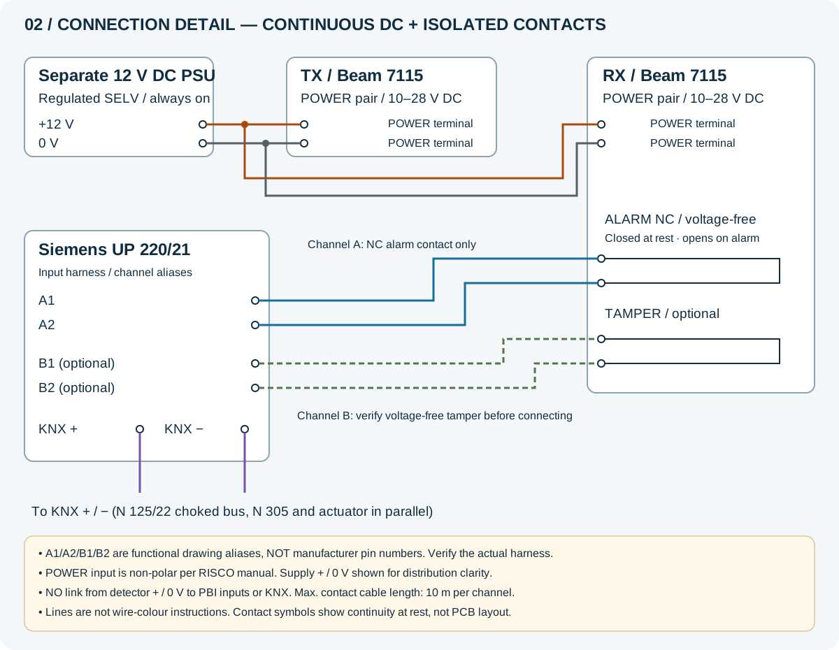
Connection schedule
| From | To | Connection requirements |
|---|---|---|
| Regulated 12 V DC supply | TX POWER and RX POWER | Permanent parallel feeds; verify voltage at each unit under load. |
| Two RX ALARM NC terminals | UP 220/21 channel A input pair | Voltage-free contact only; no connection to detector 12 V or 0 V. |
| RX TAMPER contact, optional | UP 220/21 channel B input pair | Verify a potential-free contact; report separately from the lighting event. |
| N 125/22 choked KNX output | PBI, N 305 and actuator BUS terminals | Parallel bus wiring; observe the polarity marked on each device. |
| Actuator output | Compatible lighting or indication circuit | Load supply and protection belong to the electrical design; neither PBI nor N 305 powers the load. |
This is a reference interconnection design for the identified components, not a site-specific panel construction drawing. Check terminals, revisions and harness against the actual hardware before wiring. Mains and load wiring require an authorised electrician and the manufacturers’ instructions.
What else is required?
- A continuous regulated 12 V DC SELV supply with protection and sufficient capacity after tolerances and design margin. 22 mA is the sum of the detector’s nominal consumption figures, not a standalone recommended PSU rating.
- A dedicated KNX supply, such as Siemens N 125/22 640 mA, sized for every device on the line. It does not replace the 12 V detector supply.
- A KNX actuator matched to the actual load, KNX cable, contact pairs, power cables, enclosures and suitable cable entries.
- ETS commissioning, optical alignment and handover checks. Operation during a power failure requires backup for both detector power and the control system.
04 / ETS & HANDOVER
Programming example: beam crossing switches path lighting
Example group addresses only — allocate unused addresses in the actual project. Event mode can send ON followed by OFF; verify how repeated crossings affect the running program.
| Example address | Signal | Data type | Proposed setting |
|---|---|---|---|
| 1/1/1 | Beam interrupted | 1 bit / DPT 1.001 | PBI A → N 305; 1 when NC opens, 0 on return to rest |
| 1/1/2 | Path light command | 1 bit / DPT 1.001 | N 305 → actuator; immediate ON, OFF after 120 seconds in this example |
| 1/1/3 | Cover tamper | 1 bit / DPT 1.005 | PBI B → tamper indication, if wired |
Configure channel A for NC contact-state monitoring rather than long-press operation. In N 305 select an event program triggered by value 1. Decide whether repeated telegrams restart a sequence, are ignored while running or extend a staircase timer in the actuator. Do not promise automatic retriggering without checking the selected application.
Handover checks
- Measure continuous TX and RX supply, including cable voltage drop, and verify it stays within the detector limits.
- Align TX/RX over a clear line of sight and perform crossing tests at different points and walking speeds.
- Verify NC closed at rest, open on detection and return to rest; inspect telegrams in ETS.
- Test lighting, switch-off delay, repeated crossings, cover tamper and recovery after a supply failure.
- Record models, group addresses, timing and limitations. A single beam pair does not establish direction or count people.
Installation conditions and limits
Mount TX and RX on stable surfaces with a clear path, avoiding vegetation and other obstructions. Follow RISCO instructions on direct sunlight. IP44 does not mean protection against immersion or water jets. This integration provides automation and indication; it is not a gate safety sensor or a replacement for a supervised alarm system. A simple NC loop cannot distinguish a beam crossing from a broken wire and does not guarantee short-circuit detection.
Frequently asked questions
Does the detector work without a power supply?
No. Both TX and RX need continuous DC power. The PBI reads a dry contact and does not supply detector operating power.
Can the detector connect directly to a 29 V KNX supply?
Not the documented Beam 7115: its maximum input is 28 V DC. This reference design uses a separate 12 V DC supply.
Are all components made by Siemens?
No. The detector is RISCO; the PBI and N 305 are Siemens. This is an I Feel integration solution.
Is 15 m the permitted cable length to the PBI?
No. 15 m is the outdoor optical range. The receiver-to-UP 220/21 contact cable is limited to 10 m per channel.
05 / TECHNICAL SOURCES
Manufacturer documents behind this page
The RISCO links below contain manufacturer-authored documents hosted by third parties. Specifications apply to the reference models and document revisions. Confirm availability, hardware revision and supply scope in the quotation. No price, stock status or manufacturer approval of the combined kit is claimed.
- RISCO IR Beam 71 — Installation Guide, 5IN1310 (09/2009) ↗
- RISCO Twin Beam — manufacturer brochure (07/2009) ↗
- Siemens UP 220/21 — Operating and Mounting Instructions (04/2020) ↗
- Siemens N 305 — Technical Product Information (04/2010) ↗
- Siemens N 305 — Application 750006 (10/2016) ↗
- Siemens N 125/22 — 29 V DC, 640 mA, auxiliary output ↗
Planning a beam-triggered scene?
Send the optical distance, receiver-to-indoor-PBI cable distance, KNX PSU model and required actions. We will specify power, components and commissioning.